Home
Class E Overview and
Theory of Operation
Output Circuit Values & MOSFET ratings
High Power & Harmonic Reduction
Construction Overview
Simple 400 Watt
RF Amp for
80 meters
Using a lower power
transmitter as an
RF source (A to D converter)
Pulse Width Modulator and power supply
24 MOSFET RF Amplifier - Step by Step
Analog Modulator (Class H) and power supply
Overall Schematic of a complete modulator/power supply
![]()
|
QuickEasy Log (QELog) Amateur Radio Logging Software Other Technical Information, Articles and Schematics Comments? Contact me at: 
Copyright Notice: Commercial use of the material contained in this site, all schematic diagrams, circuits, designs and related materials is prohibited without express, written consent of the author. Amateurs may use this material at will for their own use, and are encouraged to do so :-) Note: Important Safety Notice! Please read it :-) Class E AM Transmitter Descriptions, Circuits, Etc. [Updated 10-Mar-2021]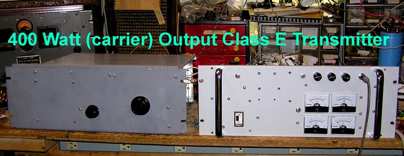
Class E Parts Available: PC Board Kits, MOSFETs, etc. Click Here for more info!Class E transmitters are high efficiency, reliable, solid-state
transmitters. They are simpler to build than similar transmitters using
vacuum tubes, and are significantly less expensive to both build and to
operate. Class E is a switching mode of operation, and exhibits
extremely linear modulation characteristics, making these amplifiers
well suited for high quality, amplitude modulation. They are also very
well suited for amplification of frequency modulation or other modes
where linear amplification is not a requirement. Class E transmitters are considered to be in the family of " Green " (environmentally friendly) technologies, since the standby power consumption is extremely low, and the operational efficiency of the system is very high when transmitting.
One of the major goals of the
class E project is to facilitate the construction, by Amateurs
with only a modest background in construction, of a high power, good
sounding AM transmitter using modern, readily available components and
at a reasonable cost. The main purpose of this site is to present a working, practical tutorial on class E transmitters (a complete explanation of class E is included), and to provide sufficient information to allow someone with reasonable radio experience, technical skills and knowledge to construct a working class E transmitter or design a transmitter using similar RF and modulation methods. The designs presented here have been reproduced many times and are proven and reliable. 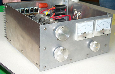
To the left:, 350 Watt class E RF amplifier built by Bob, K1KBW. This RF amplifier, combined with a modulator/power supply forms a complete 350 watt (carrier output) transmitter. |
|
Complete schematics [unless otherwise noted] of real, working
transmitters (along with pictures and technical explanations) that I
have personally built and are using on the air daily are included.
To the right: Complete, 3 band, 1kW class E transmitter. This transmitter uses a 5 MOSFET Pulse Width Modulator implemented using the Class E PWM Board Set, and can be operated up to 1kW power input. A single RF amplifier is used for 80 and 160 meter operation, and there is an individual RF ampflier for 40 meters. The 80/160 meter RF amplifier consists of 4 6-MOSFET RF amplifiers, and the 40 meter amplifier uses 4 4-MOSFET modules. One set of meters is used for all RF amplifiers, and the output of the modulator is switched between the different RF amplifiers when changing bands. Because class E RF amplifiers are relatively inexpensive to construct, switching between RF amplifiers to change bands, rather than constructing a single, bandswitched RF amplifier is very practical, and offers several operational and technical advantages. The main disadvantage to such an arrangement is the extra space required, although one could consider this an advantage, as the larger transmitter tends to look more "impressive". Employing so-called "boatanchor" - "vintage" or "classic" - construction practices (large meters, black wrinkle finishes, etc.; big relays that make a good, loud "clunk" when operated) gives the transmitter a particular look and feel. |
|
Please let me know if there are errors or if there is missing information :-) Suggestions are always welcome. |
 They
are accurate representations of what is (or was) in use on the air at
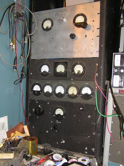
that time. The photos show various components and construction methods
They
are accurate representations of what is (or was) in use on the air at
that time. The photos show various components and construction methods